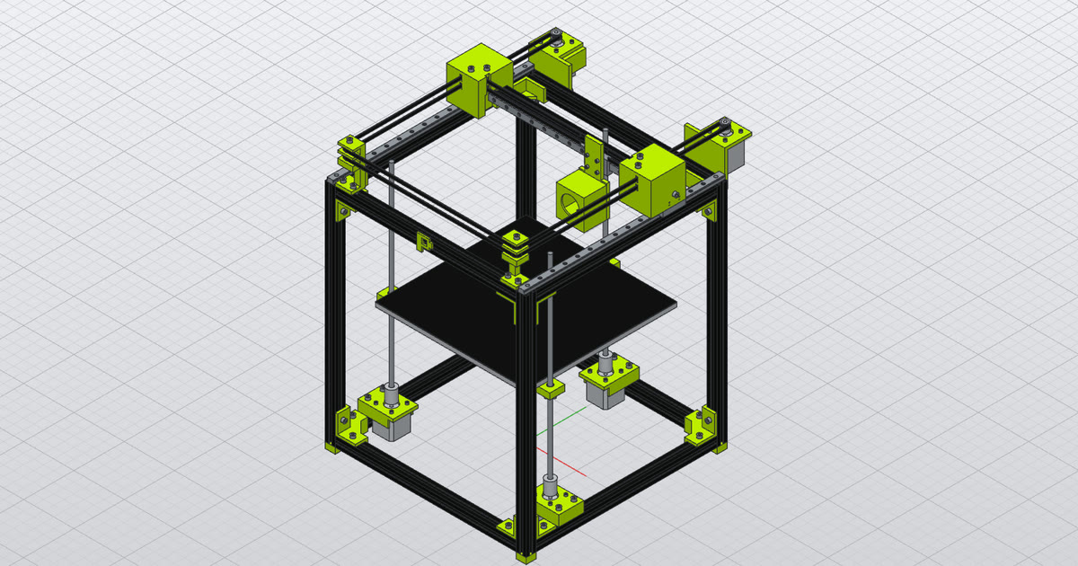
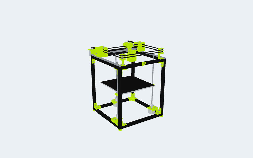
Each stage was one request to Claude Code running headless, with Polykrom's MCP server (polykrom-cli mcp --headless) as its only tool, starting from the design the stage before had saved. Times, costs and tool calls are from the agent's run records.
Errors are tool calls that came back with an error; the agent recovered from each one and reported what it worked around.
1. Frame and bedthe brief
Start a new design: the frame and bed of a CoreXY 3D printer in the style of a Voron Trident (the XY gantry fixed at the top, the bed moving down on three lead screws). Frame: 2020 extrusions from the library (parts.insert family extrusion, size 2020): four vertical posts 450 mm long at the corners of a 400 x 400 mm footprint (outer faces flush with it), and eight horizontal members between the posts at the bottom and at the top (360 mm). Hold the corners together with 3D-printed corner brackets: at each of the eight corners a printed bracket that wraps the joint, each with M5 socket head cap screws (library) through it into the extrusions' slots or core. Four printed feet under the posts. Give the front a logo: Polykrom's pixel p, a printed badge made of 5 mm square cells, 6 cells tall, rows from the top '#####.', '##..##', '##..##', '#####.', '##....', '##....' (# is a cell), standing out 3 mm, mounted on the front of the top front extrusion, centred. Ground the frame (a grounded component named Frame holding its extrusions, brackets, feet, screws and the badge, or grounded subcomponents rigidly joined). Bed: an aluminium plate 300 x 300 x 8 in a component named Bed, centred, its top 380 mm above the frame's bottom, with a 1 mm black print surface on top. Report the frame's outer dimensions, its mass, a cut list, and how many brackets and screws you used.
2. XY motionthe brief
Open s1_frame.polykrom (a CoreXY printer frame with its bed). Add the XY motion, every part held: Y: an MGN12 rail 400 long on top of each of the two top extrusions that run along Y (left and right; extend them to the frame's outer edge if needed), fastened with M3 screws through its holes, each with an MGN12H carriage. Gantry: a 2020 extrusion along X joined to the two Y carriages by printed gantry joiners (one on each carriage, screwed to the carriage's M3 holes and to the extrusion), in a component named Gantry with those carriages and joiners; a slider joint named Y between the Frame and the Gantry, axis +Y. X: an MGN12 rail 350 long screwed to the gantry's front face, an MGN12H carriage on it, and a printed X-carriage plate on that carrying the toolhead: a printed shroud about 55 x 45 x 60, an aluminium heater block and a brass nozzle (a cone about 10 mm ending in a point), all in a component named Toolhead; a slider joint named X between the Gantry and the Toolhead, axis +X. Motors: two NEMA17-48 steppers at the two rear top corners on printed motor mounts (each mount screwed to the frame, the motor screwed to the mount with four M3 screws into its tapped holes), shafts vertical, a GT2 20T-5 pulley on each shaft; revolute joints named A (rear left) and B (rear right) about their shafts. Belts and idlers: idlers of stacked 625 bearings (library) on M5 screws in printed idler mounts at the two front top corners and at both ends of the gantry, and the two GT2 belts as thin solids (6 mm wide, 1.4 mm thick) along the CoreXY path at two heights, from each motor's pulley round the idlers to the X carriage: the belts are part of the picture, not of the kinematics. CoreXY: motion links that follow two joints (joint.motion_link with `also`): X follows (A + B) / 2 and Y follows (A - B) / 2, in mm of belt per degree (parts.library gt2_pulley: belt_mm_per_deg). Verify by driving: A = B = 360 deg moves the toolhead along X only, A = -B = 360 deg along Y only. Report what you measured, then put the joints back to 0, and check that nothing overlaps (inspect.interference) except fasteners in their holes.
3. Z axisthe brief
Open s2_xy.polykrom (a CoreXY printer with its XY motion). Add the Z axis, every part held: three NEMA17-40 steppers under the bed at its front left, front right and rear centre, each on a printed Z motor mount screwed to a bottom extrusion, shaft up; a shaft coupler (an aluminium cylinder 20 mm across, 25 long) joining each motor shaft to a T8 lead screw 400 long; a T8 lead nut on each screw, screwed into a printed bed bracket that carries the bed (the brackets fastened to the bed). The bed moves on a slider joint named Z between the Frame and the Bed (axis +Z), driven by a revolute joint named Zmotor (the front left motor) through joint.screw with the T8's lead (8 mm per turn); the other two motors and their screws turn with it (motion links). Verify: one turn of Zmotor moves the bed 8 mm and turns all three screws. Check that nothing overlaps except fasteners in their holes, and report the masses of the printed parts together.
4. Verify it as a machinethe brief
Open s3_z.polykrom (a complete CoreXY printer: gantry on joint Y, toolhead on joint X, motors A and B driving X and Y through CoreXY motion links, the bed on joint Z driven by Zmotor through lead screws). Verify it as a machine. 1. Travel: with joint sweeps (sweep a motor where a joint follows it), find how far X, Y and Z can go both ways before anything collides or a carriage would leave its rail, and set the joints' limits to that range. 2. Build volume: the box the nozzle tip can reach above the bed's print surface (X x Y x Z ranges); is it at least 250 x 250 x 250 mm? If not, change the design until it is, and say what you changed. 3. Collisions: a motion study named Corners keyed on A, B and Zmotor that takes the nozzle to the eight corners of the build volume; check it for interference and fix anything that collides. 4. The bill of materials (assembly.bom) by part and quantity, the total mass, the printed parts' mass, and the centre of mass.
5. Make it printthe brief
Open s4_verify.polykrom (a verified CoreXY 3D printer: A and B are the XY motors, Zmotor the bed's lead screws; X and Y follow A and B through CoreXY links). Make it print: a motion study named Print of 240 steps, keyed only on A, B and Zmotor (never on X or Y directly), in which the nozzle draws a 100 mm square centred on the bed three times, the first layer with the tip 0.2 mm above the print surface and each next layer 0.2 mm higher. Work out the motor angles for each corner from the CoreXY relations. Check it for interference. Trace the nozzle tip's path and report the square's side lengths and the corners' heights above the print surface. Export the animation as a GIF to corexy-print.gif (900 x 600), and give the motor angles you used for the first layer's corners.
6. Showcasethe brief
Open s5_print.polykrom (the finished CoreXY printer, in Polykrom's colours: black frame, lime printed parts, the pixel p badge on the front). Make its showcase pictures: put the joints at a pose that shows the machine well (the toolhead off centre, the bed partway down); render it in the render workspace (render.preflight, render.start, render.status until done, render.export) to printer-render.png at 1600 x 1000 from a three-quarter front view that shows the badge, and export the bill of materials as CSV to printer-bom.csv. Report the render's settings and the BOM's line count. Check before you finish that every part still has its colour.
every briefended with
Units are millimetres and degrees; Z is up. Work only through the Polykrom tools. Standard hardware comes from the parts library: parts.library lists the families (extrusion, stepper, gt2_pulley, linear_rail, linear_carriage, lead_screw, lead_nut, bearing, socket_head_cap_screw, hex_nut, washer...), with their dimensions. Everything has to make physical sense: every part is held by something (a bracket, a fastener, a joint), nothing floats and nothing overlaps another part except fasteners in their holes; parts that a real printer would 3D-print (brackets, mounts, joiners, the toolhead shroud) are modelled as their own components in PLA. Colours, Polykrom's: the aluminium frame anodised black (#111111), every printed part lime (#CCFF00), the bed's print surface black, metal hardware left as metal (appearance.assign). When the stage is done and you have verified it, save the design to <the stage’s file> and reply with a short report: what you did, the numbers you verified, and anything that did not work or that you had to work around.