Showcase · Kestrel

A robot arm, designed by an AI agent in Polykrom, then checked by everything but its word.

Seven plain-language briefs, one agent, Polykrom's MCP tools and nothing else. Kestrel is a desktop pick-and-place arm: a gear-driven turntable, shoulder and elbow, a coupled parallel gripper, standard hardware from the library, a motion study, a stress study and a robot description for simulators. Every number below was re-measured on the saved design by an independent script. The last section lists what this version can't do yet.

Loading Kestrel…
step 0yaw 0°shoulder 0°elbow 0°grip 40 mm

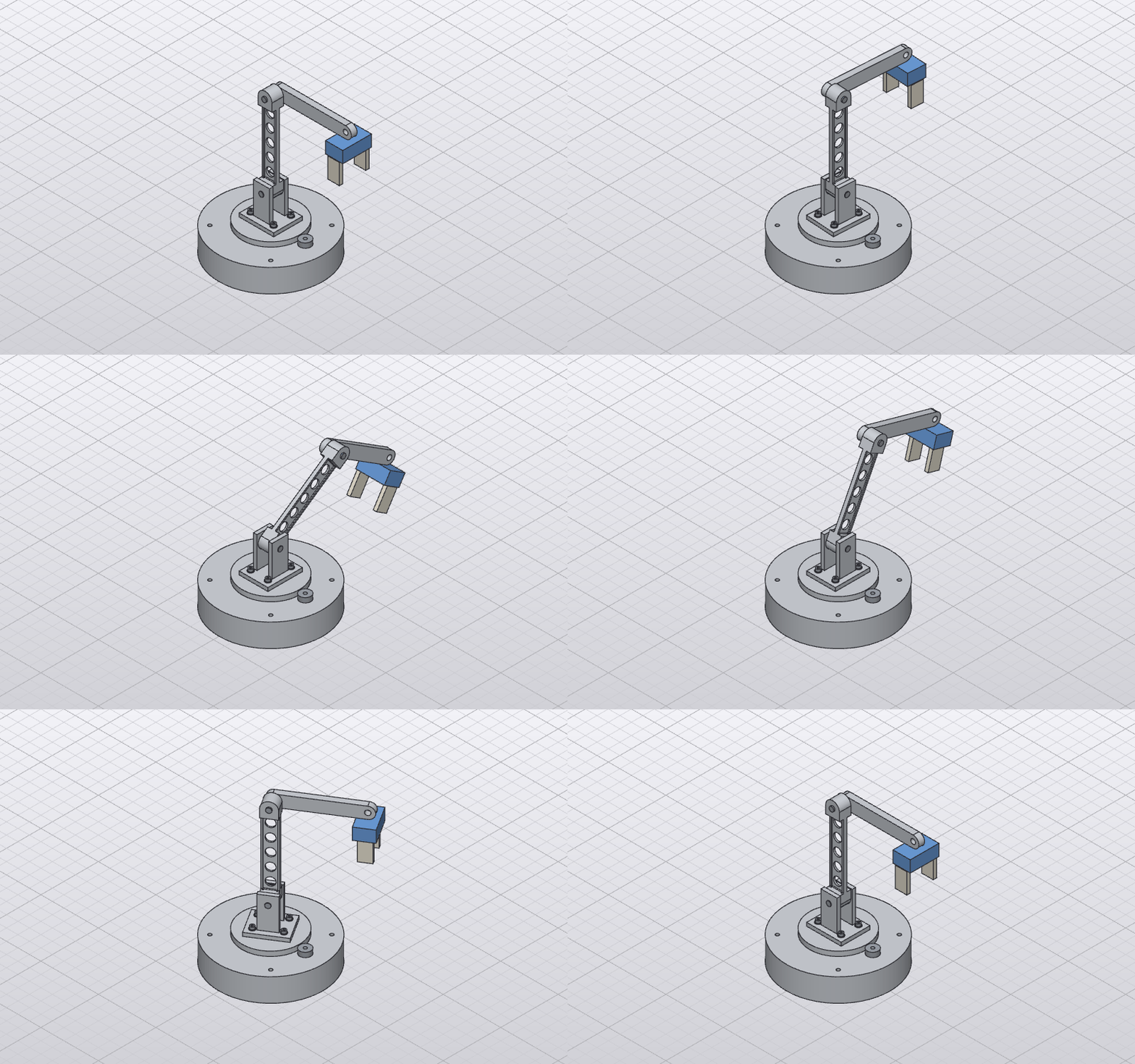
Live: the URDF Polykrom exported (one mesh per part, joints in metres) driven by the motion study's recorded joint values. Drag to orbit, scroll to zoom.

7
briefs, one agent
21
bodies in 21 parts
6+2
joints + gear & jaw links
1.54 kg
from real materials
28 min
agent time, all stages
$10
model cost, all stages

How it was built

Each stage was one request to Claude Code running headless with Polykrom's MCP server as its only tool. It had no file system, no shell and no help. After each stage, a separate script opened the saved .polykrom file and replayed drives, sweeps and measurements to confirm the claims.

1. Base and yaw drive81 s + 96 s first try18 tool calls$0.72

A Ø180 aluminium base with a bearing seat, a NEMA 17 motor, a 20 mm pinion and a 100 mm turntable gear, coupled 5:1.

  • verifiedVolumes within 5 mm³ of hand calculations
  • verifiedPinion 360° → turntable −72.000°, gear link ratio −0.2
  • verifiedNo interference over a full pinion turn
  • notedFirst attempt: it caught three errors in the brief and stopped (below)
  • notedDefault sweep step too costly; re-ran at 5°
2. Shoulder, upper arm, forearm327 s39 tool calls$1.50

A yoke on the turntable, a 140 mm upper arm with lightening holes, a 120 mm forearm, and steel pins in 8.2 mm bores.

  • verified0.100 mm radial clearance on all four pin fits
  • verifiedJoint limits from contact sweeps: shoulder −114.9…+114.5°, elbow −77.4…+257.4°
  • verifiedNo interference at rest or at each limit
  • notedWhole-assembly sweeps hit the collision budget, so it swept part pairs one at a time
  • notedCombined limits collide (reported, not fixable with per-joint limits)
3. Parallel gripper84 s22 tool calls$0.83

A PLA wrist with two nylon jaws on sliders, coupled by a motion link.

  • verifiedJaw L 15 mm → Jaw R 15 mm, gap 40 → 10.0 mm
  • verifiedNo collisions over the full travel
  • notedIt set the link ratio to +1, not the −1 we suggested, because its slider axes point inwards
4. Hardware, materials, BOM238 s47 tool calls$2.18

A 608 bearing, four ISO 4762 M4×12 screws and four ISO 7089 washers from the library, with real materials on every body.

  • verified21 bodies, all Aluminium, Steel, PLA or Nylon
  • verified1,645 g total, 430 g moving
  • verifiedOnly overlaps: four 20.9 mm³ thread bands
  • verified15-line BOM
  • notedIt caught a fourth error in the brief: the cheeks covered the screw holes
  • notedLibrary parts needed their material, name and orientation fixed by hand
5. Pick-and-place motion195 s27 tool calls$1.14

A 120-step study: swing 90° through the gear train, reach down, grip, lift, return, release.

  • verifiedLowest tool point 42.9 mm above the table, 182.9 mm reach (motion.trace)
  • verifiedNo collisions between moving parts
  • verifiedGIF and URDF exported (22 links)
  • notedAll-pairs collision check ran out of budget, so it checked in groups
  • notedURDF lacks gear and jaw couplings (no mimic tags)
6. Is the arm strong enough?50 s9 tool calls$0.50

Static stress on the upper arm, held at the shoulder, with 40 N square to it at the elbow.

  • verifiedSF 43.4, 0.034 mm deflection (re-run independently: 43.40, 0.034)
  • verifiedConverged over three meshes; hand calculation agrees
  • notedIt noted the arm was about 15× oversized but didn't change it unasked
7. Make it light612 s55 tool calls$2.65

Lighten the upper arm while keeping SF ≥ 3 and deflection < 0.2 mm, without touching its fits.

  • verified181.8 g → 73.3 g (−60%) in six FEA iterations
  • verifiedSF 10.7, 0.128 mm deflection (re-run independently: 10.75, 0.128)
  • verifiedAll fits and limits re-checked
  • notedFound that the elbow's −77.4° limit (from stage 2) now collides with the gripper at −67.7°
  • notedKernel refused 1 mm fillets on the web edges

It caught four mistakes in our own brief

The briefs were written quickly, on purpose, the way people actually ask. The agent built what was asked, measured it, and reported where the brief couldn't work. It never quietly changed the design to hide a problem.

The motor didn't fit

A 42.3 mm NEMA 17 centred 60 mm out reaches 81.15 mm, past the 66 mm inside wall of a Ø140 base. It found the overlap (6,194 mm³) and offered three fixes. We enlarged the base.

The bearing seat broke through

A 7 mm pocket in a 4 mm top is a hole, not a seat. We added a hub under it.

Tapped holes went right through

8 mm deep in an 8 mm disc. They became 6 mm, leaving 5.2 mm of thread engaged for the M4 screws.

The cheeks covered the screw holes

Half of each yoke-plate hole sat under a cheek, so no screw head could seat. It shortened the cheeks from 40 to 28 mm, checked that the arm still clears them, and explained the alternative.

What it exercised

One small robot touches most of the app.

Parametric parts

  • Shells, pockets, holes, circular hole patterns
  • Rounded links with lightening holes
  • Gear blanks with bores and spigots

Assemblies

  • 21 components, one grounded
  • Rigid, revolute and slider joints
  • A gear link (pitch radii 10 and 50: ratio −0.2) and a jaw motion link

Standard hardware

  • 608 bearing in its seat
  • 4 × ISO 4762 M4×12, 4 × ISO 7089 M4
  • Bill of materials as CSV

Fit and clearance

  • 0.1 mm radial pin clearances, measured
  • Joint limits from contact sweeps: shoulder −114.9°…+114.5°, elbow −77.4°…+257.4°
  • Interference across all 21 bodies

Motion

  • A 120-step pick-and-place study
  • Collision checks over the study
  • A tool-tip trace (lowest point 42.9 mm, reach 182.9 mm)
  • A GIF of the cycle

Engineering output

  • Static stress on the upper arm (MFEM, via Nightfall)
  • Mass from materials: 1,645 g, 430 g moving
  • URDF with masses, inertias and limits

Is the upper arm strong enough?

The brief asked for SF ≥ 3 and less than 0.2 mm deflection, with 40 N square to the arm at the elbow, its worst case. The first result was SF 43. So in stage 7 the agent was asked to make it as light as it reasonably could without touching any fit. It ran the solver after every change.

#ChangeMass (g)Safety factorDeflection (mm)
0As built in stage 2181.843.40.034
1Pockets from both sides: 4 mm flanges and web119.146.00.042
2Flanges and web 2.5 mm97.342.00.054
3Mid-section thinned to 12 mm85.219.20.075
4Mid-section 8 mm79.211.10.097
5Mid-section 6 mm, five Ø14 web holes73.310.50.129
6R1 fillets at the pocket steps (final)73.310.70.128

Linear static FEA through Nightfall (Netgen mesh, MFEM solve). The final run was converged over three meshes down to 0.89 mm: deflection 0.1281 / 0.1283 / 0.1284 mm. The fillets were added because the peak stress kept rising with mesh refinement at the sharp steps. An independent re-run of the saved part gave SF 10.75, 25.7 MPa peak and 0.128 mm. The fits stayed exactly as they were: Ø8.200 holes at 140.000 mm, R12 ends, full 20 mm thickness at the pins.

The cycle, as Polykrom renders it

The animation the agent exported with motion.export_animation: 121 frames from the headless renderer.

Kestrel swings 90 degrees, reaches down, closes its gripper, lifts and returns

Where this version falls short

Found by building Kestrel, not by guessing. Several were fixed the same day; the rest are on the roadmap.

Fit sweeps

A joint sweep can't turn a pin in a hole with 0.1 mm of clearance. It runs out of its collision budget, even for that one pair.

That's exactly the fit a sweep exists to check. The agent swept the other part pairs one at a time and checked the pins statically instead. → #25

Motion checks

Checking a 21-body study for collisions, all pairs at once, stops at step 0.

The work budget runs out, and any part that overlaps from the start (a thread in a tapped hole) eats it. The agent split the check into groups and sampled arm-against-base every 4th step. Pairs that touch at the start should be set aside, as joint sweeps already do. → #25

Limits

Joint limits are per joint, and nothing re-checks them when the assembly changes.

Each limit is safe on its own, but shoulder +114.5° with elbow −77.4° drives the forearm 2,661 mm³ into the yoke. There are no coupled limits or reachable-workspace check yet.

The elbow's −77.4° limit was swept in stage 2, before the gripper existed. Once the gripper was on, the wrist hit the upper arm at −67.7°. Polykrom didn't flag the stale limit; the agent found it in stage 7. It is the one value we changed by hand after the build. → #25

Kernel

The kernel refused 1 mm fillets along the upper arm's web-to-flange edges, so those stay sharp.

Contact checks that run on meshes also raised a false 0.022 mm "contact" on a pin with a true 0.100 mm gap, from the mesh's 0.16 mm chord tolerance. The exact check was right. → #25

Parts library

Library parts arrive with a placeholder material and bodies named Body1–9.

The 608 bearing seated facing out of its pocket and had to be flipped. It is a solid envelope, so in steel it weighs 18 g against a real bearing's 12 g. The screws seated on the plate rather than on their washers and were raised 0.8 mm by hand. → #43

Simulators

The URDF has no <mimic> tags.

The gear between pinion and turntable, and the link between the jaws, are lost in simulators. Effort and velocity limits fall back to defaults because parts don't carry actuator specs yet. → #27

Results on the part

Stress comes back as numbers, not colours on the part.

Nightfall now writes the surface field. Drawing it on the body is in progress. → #29

Gears

Gears are pitch-diameter blanks, not teeth.

The kinematics are exact, but there's no tooth contact or backlash to check. → #26

Visuals

The exported animation is flat grey.

The headless renderer ignores material appearance, so the 3D view above is the better picture. → #33

Fixed today

Building the earlier test assemblies found three bugs, all fixed:

  • A screw couldn't seat on a washer that was itself seated: the insert mixed up world and part coordinates.
  • A joint's named face could resolve on another part modelled at the same local coordinates.
  • An occurrence couldn't be named by its component.

→ #17

Take it apart yourself

The design, the robot description, the bill of materials and the agent's own reports.